Chapter 1
explains that HF, VHF, and UHF radio waves have different
propagation
characteristics. VHF and UHF radio frequencies propa-
gate principally
along LOS paths. On the other hand, HF waves, those
below 30
MHz, can also reflect off the ionosphere and then travel back to
earth. These
sky waves, as they are called, give rise to one of the most
important
attributes of HF radio and that is beyond the line of sight (BLOS) communication.
Volume One, “HF Technology”, of this series “Radio
Communications
in the Digital Age” provides a detailed description of HF
propagation.
This chapter deals primarily with LOS propagation characteris-
tics of the
VHF and UHF frequency bands.
While many
HF propagation characteristics are associated with the ionos-
phere and
wave reflections from it, the effects of local area topography
and conditions
in the lower atmosphere mostly govern VHF and UHF propa-
gation. Similarly,
ground wave propagation is a very important mode of HF
wave propagation,
but at frequencies above 30 MHz, ground waves are
absorbed
almost immediately and have a negligible beneficial impact.
Frequencies
in the VHF and UHF bands usually penetrate the ionosphere and
speed out
into space. That means that reflection off the ionosphere can not
be used to
reliably extend communications range of these frequencies. For
the most
part, the transmitting and receiving antennas must have a fairly
unobstructed
path between them for communication to take place, hence
the term
line- of- sight (LOS).

Height Matters for LOS Range
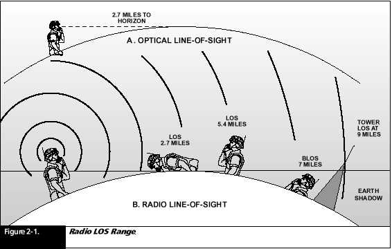
The visible horizon observed at approximately five feet above a flat surface of earth is less than 2.7 miles away (Figure 2- 1). This is approximately the maximum LOS radio range from a manpack radio on the back of a standing man to another manpack radio that is lying on the ground.
Figure 2- 1 shows that if the receiving radio were elevated to the back of a standing man, this maximum distance would be doubled. In this case the LOS distance would be 5.4 miles. But, if the second man was standing beyond this distance, say at 7 miles from the transmitting radio, the shadowing effects of the earth’s curvature would prevent the second man from receiving the radio wave. In this case, 7 miles is BLOS and is not within reach of VHF or UHF radios in these positions.
It is clear
that the elevation of both the transmitting and receiving antennas is crucially
important. For example if the receiving antenna were mounted on a 26- foot
tower, the total LOS distance would be increased to 9 miles. Of course
if the radiomen were both located on the tops of mountains, the LOS range
might be as much as from 50 to hundred miles.
For ground-
to- air UHF communications, the aircraft can be 100 miles away
or more and
still maintain contact.
Transmit Power and Radio Range
For HF radio
communications, transmit power is an important item. For very
long distances,
particularly for both skywave and ground wave propagation,
every mile
of distance attenuates (decreases) the signal. For most systems,
when doubling
the distance, the radiated signal is divided by four!
Therefore,
transmit power is often the limiting range factor. It is common to see
500- watt and 1- kW HF transmitters in vehicular or shipboard HF applications,
and 10- kW or greater for HF fixed station broadcast sites.
VHF and UHF
waves are also attenuated with every mile of distance. However,
for tactical
manpack applications, it is most often the shadowing effects of irregular
terrain, buildings, and other objects that limit the effective range and
not transmit power.
Many manpack
radios have two power settings: 2 Watts and 5 to 10- Watts.
The 2- Watt
setting is often adequate and extends battery life when this
power level
is selected. On the other hand, there are situations where
increased
power is beneficial. In urban areas where high radio frequency
noise is
prevalent, higher power increases the signal- to- noise (SNR) ratio and
improves reception. Also, modern high data rate modulation wave-
forms require
a high SNR to be effective.
UHF ground-
to- air communications benefit from higher power because the
typical range
is 100- miles or more. Lastly, although tactical manpack UHF SATCOM radios
with only 18- Watts located in Europe can contact a satellite in an orbit
22,000 miles above the earth’s equator, communication is more reliable
when higher power is used.
These higher
power VHF and UHF radio sets are typically mounted in vehicles
or fixed
stations with 50- watt power amplifiers to boost the power of the
manpack transceiver.

VHF and UHF Radio Reception Behind Ridges
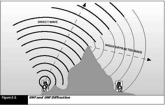
For the most part, ridges and hills form shadows of VHF and UHF radio waves. However, there is an important exception when it comes to very sharp ridges or other kinds of abrupt barriers. This is caused by a phenomenon known as Diffraction (Figure 2- 2). When a VHF or UHF wave comes to a sharp edge, a portion of the wave bends around the edge and continues propagation as if a very low power radio was placed at the top of the ridge. It is important that the ridge be relatively sharp. A well- rounded hill or the curvature of the earth is not sufficient to cause this effect. This effect is important in a battle field situation where a soldier must seek shelter behind a ridge.

Reflections and Multipath Distortion
VHF and UHF
waves can be reflected off of dense surfaces like rocks or
conductive
earth, just like a beam of light can be reflected off a wall or a ceiling.
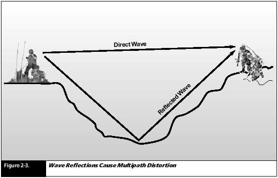
Sometimes several paths exist between a transmitting and receiving antenna
(Figure 2- 3). In this figure there is a direct LOS path between two radios,
but there is also a reflected path from the bottom of a valley between
them. It is clear that these two paths are of different length, and that
the direct path is the shorter of the two. Since radio waves travel at
a constant velocity, the direct path wave arrives at the receiver before
the reflected path. This means that the same broadcast information reaches
the receiver at two different times. The effect of this is much like echoes
that one hears in an acoustically poor room. If the echoes are close enough
to each other, it is hard to understand what is being said. In radio terminology,
this is called multipath distortion.
Although
it is annoying with voice communications, it is devastating to high data
rate digital communication. A subsequent chapter will discuss some of the
ingenious ways that have been devised to minimize the effects of this type
of distortion. “Picket fencing” is a form of multipathing common to vehicular
mounted radios. It is prevalent with VHF and UHF. The higher the frequency,
the more pronounced the effect is. It is usually caused by interference
or reflections of signals from man- made objects such as buildings, houses,
and other structures. These objects cause constructive and destructive
fields (or strengthened and weakened signals) so that when a vehicle travels
through these fields, it receives
alternately
stronger and weaker signals. There is usually a “swishing” sound in the
receiver, as the signals rapidly grow weaker, then stronger, then weaker
again.
The signal
peaks and nulls are a function of wavelength. A 450- MHz signal
being received
on board a vehicle travelling at 60 mph can “flutter” very
rapidly as
the vehicle travels through the downtown area of a city. You can
experience
the same phenomenon on the lower VHF bands, but the flutters
are not quite
as rapid.
Sometimes
this same effect is caused by signals of two stationary radios
reflecting
off a moving aircraft above them. Multipath within a Building In tactical
situations, manpack radios are frequently operated under cover in
buildings.
VHF and UHF waves have trouble penetrating reinforced concrete
exterior
walls, but they pass through windows and light interior wall partitions
with comparative ease.

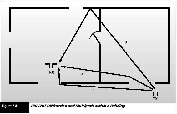
Figure 2- 4 shows a receiver in a room of a building with a transmitter located outside. In this case, there are three paths from the transmitter to the receiver, and none of them are direct.
Path 1 passes
through the window nearest the receiver location, and is
diffracted
around the sharp edge of the window frame to the receiver.
Likewise,
path 2 just misses having a direct path to the receiver. It is
diffracted
slightly by the window frame nearest the transmitter and then
passes through
an interior wall on the way to the receiver. Path 3 goes
through a
window and an interior wall before striking an outside wall of
the building
and then reflecting back to the receiver.
Each of these
paths has a different distance and, therefore, can cause
multipath
distortion. Frequently just moving the receiver a few feet in some direction
will avoid one or more of the available paths and the reception of the
signal may be greatly improved.
VHF and UHF Wave Ducting
The suggested
limits on LOS range are sometimes exceeded in practice.
One of the
principal reasons for this is an effect called “ducting.” VHF
and UHF waves
traveling through the atmosphere travel slightly slower
than they
do in free space, and that is because the density of air slows
them down.
The denser the air, the slower the wave speed through it.
Under normal
conditions, the density of air is the greatest at the surface
of the earth
and gradually reduces in density with altitude. Under fair, dry, and moderate
weather conditions; the slight variations in air density have negligible
effects on the path of radio waves passing through it.
Frequently
there are abrupt changes in air density due to weather fronts
passing over
an area or the heavy moisture burden of rain clouds. In such
cases VHF
and UHF can bend or duct between air layers of different densities. Sometimes
this ducting bends the radio waves downward so that the radio waves tend
to follow the curvature of the earth. In such cases the LOS range is considerably
greater than the optical LOS range. This type of wave propagation is impossible
to predict; it is not practical to
plan on it
for range improvement. However, when ducting conditions exit,
they generally
do so for hours at a time.
SUMMARY
HF propagation
can be LOS through ground waves or direct waves
and BLOS
though the use of sky waves.
VHF and UHF
frequencies cannot make use of skywave or ground
wave propagation
and depend almost exclusively on the direct
wave. This
restricts their use to LOS communications.
Radio wave
propagation at VHF and UHF frequencies are primarily
affected
by local area topography (hills and valleys) and atmospheric
conditions.
VHF and UHF
range is usually limited by physical wave shadowing
of obstructions
such as buildings and mountains.
Diffraction
of VHF and UHF waves can bend them around sharp
edges such
as window frames or sharp ridges.
Multipath
distortion is caused by waves arriving at a receiver from
more than
one path.
LOS range
is greatly improved with increased height of either
(or both)
transmit or receive antennas.
Ducting caused
by certain weather conditions can sometimes
increase
the range of VHF and UHF waves.