The increased requirement for greater troop mobility has been accommodated by the trend toward multiband, multimode radio systems. While technology permits the production of smaller, lighter- weight radio equipment, overall communications capability has not kept up with the demand. The need for flexibility, security, and reliability of terrestrial radio communications remains a critical problem.
The two most
significant radio limitations are the congested frequency
spectrum
and the physical limits on radio wave propagation. The develop-
ment and
use of communications satellites are an attempt to overcome
these limitations.
Even as there
is a need for HF, VHF, and UHF radio in the tactical
environment,
there is also a need for different types of satellite systems.
These can
also be grouped by frequency bands as follows: Ultra High
Frequency
(UHF), Super High Frequency (SHF), and Extra High Frequency
(EHF).
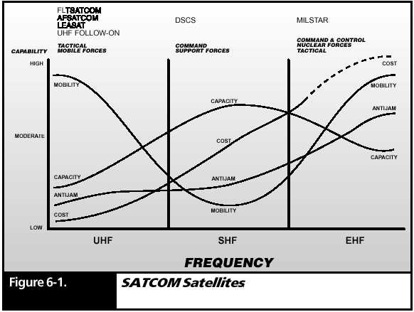
Figure 6-
1 summarizes the chief characteristics of these three
groups. Figure
6- 1 shows that the outstanding characteristics of the UHF group are the
mobility of the ground terminals and its overall lower cost.
It is this group that is used by our tactical mobile forces. The SATCOM discussions in this volume will be limited to this UHF Satellite system.
A Communications Satellite is a Radio Repeater
Just as cell
phones use radio repeaters placed on towers and tall buildings
to increase
area coverage, SATCOM transceivers achieve coverage by
using radio
repeaters placed in satellites.
Technically,
any ground radio with no obstructions above it is within the
LOS of any
satellite that is above the horizon. Chapter 2 stressed the
advantage
that antenna height makes in extending LOS distance. A satellite is the
ultimate high antenna tower.
UHF is an
excellent candidate frequency to contact a satellite because it
can penetrate
the atmosphere and ionosphere with little attenuation.
Uplink and Downlink Frequencies
The function
of a repeater is to receive a radio signal at a particular
frequency,
amplify it, and then convert it to another frequency for
rebroadcast.
The radio paths up and back from a satellite are called
uplinks and
downlinks.
Different
uplink and downlink frequencies are required to avoid feedback
between the
satellite transmitter and receiver. UHF uplink frequencies
range from
292.95 MHz to 310.95 MHz, while downlink frequency range from 250.45 MHz
to 269.95 MHz.
Uplink and
downlink frequencies are paired within specific channel groups
and frequency
plans within that group. For example, Channel 2, Plan A,
specifies
an uplink frequency of 251.95 MHz and a downlink frequency
of 292.95.
SATCOM transceivers can be programmed so that when in the SATCOM mode, a transceiver adjusted for a given channel will automatically choose the correct uplink and downlink frequencies for transmitting and receiving.
The Geostationary Orbit, and Coverage Footprint
The laws of
physics are such that the speed of a stable satellite orbit
depends upon
its distance above the earth. If a satellite is placed in a
stable orbit
22,300 miles above the equator, it must travel just fast enough to make
a rotation around the earth in 24 hours. Since that is exactly the same
speed that the earth rotates, a satellite placed in that orbit will hover
over the same spot on earth as they both rotate together. This is called
a geostationary orbit. Satellites closer to the earth must travel faster
to remain in orbit and their positions would drift around the earth to
the east.
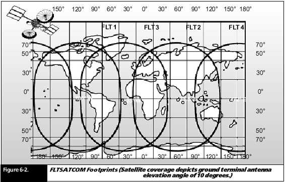
A great advantage
of having a communications satellite in a geostationary
orbit is
that it has a fixed, huge LOS coverage area. Figure 6- 2 represents overlapping
LOS areas created by having four such satellites evenly distributed around
the earth above the equator. These LOS areas are
called footprints
of the satellite. Just four of these satellites provide footprints that
cover the earth from the latitudes of 70° north to 70° south.
A ground transceiver
located anywhere within a footprint can link with
the associated
satellite, and then back down to any other transceiver
located within
the footprint. For example, Figure 6- 2 shows that a
transceiver
located anywhere in North America can link with a transceiver
located anywhere
in South America.
Many locations
are under two adjacent footprints. This gives two possible
satellite
path choices. For example, a transceiver located near the East
Coast of
the US is within the footprints of both satellites FLT1 and FLT3.
The footprint
of FLT3 includes all of Europe and Africa. Being able to
use both
of these footprints provides a range that includes most the US,
South America,
Europe, and Africa.
With the use
of ground repeating relay stations, the communication range
of a SATCOM
transceiver can have worldwide coverage.
SATCOM Antennas
The bad news
about geostationary satellites is that they must be 23,300
miles above
the earths equator. That is a very long LOS distance for a
relatively
low power UHF transceiver. (Manpack SATCOM transceivers
are generally
limited to 20 watts or less of transmit signal power.)
The good
news about geostationary satellites is that their exact location
is known,
so the LOS direction to it from any place within its footprint
can be calculated.
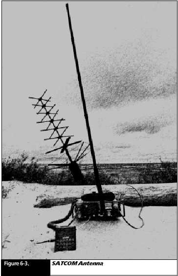
To make the
most of both the good and bad news, the antennas used
for SATCOM
work are directional (Figure 6- 3). That is, they are constructed with
a reflector similar to those used in a flashlight to focus the beam.
By focusing
the beam of a directional antenna, you can boost the effective
radiated
power by four times or more. Ground troops in a given theater
of operation
are told the precise compass bearing and elevation to aim
the antenna
so that it points directly toward the desired satellite.
To achieve
a greater margin of link closure, vehicular and fixed station
applications
usually include adapters that provide amplification of the
manpack transmit
signal to 50 watts.
UHF SATCOM Channel Characteristics
As an example of UHF SATCOM channel characteristics, the U. S. Navy has a group of satellites called Fleet SATCOM (FLTSATCOM) frequency channels. The channel capabilities of a FLTSATCOM satellite are as follows:
One 25- kHz channel downlink with a special 15 kHz SHF uplink dedicated to Navy fleet broadcast use.
Nine 25- kHz relay channels for general use.
Twelve Air Force narrowband, 5- kHz channels.
One DOD wideband, 500- kHz channel for special use.
The fleet
broadcast channel mentioned above is a one- way, shore- to- ship
channel of
25- kHz bandwidth, which supports 15 time- division multiplexed, 100 wpm
Teletype circuits. Its uplink is transmitted as an anti- jam protected
SFH signal, which is then processed, and frequency translated to a UHF
downlink by circuits within the satellite.
The nine 25-
kHz channels for general use are dedicated to FM modulated
signals.
Any data waveform that results in an FM, 25- kHz bandwidth can
take advantage
of these channels.
Demand Assigned Multiple Access (DAMA)
The few channels
available from each satellite require that strict controls
must be enforced
about sharing. Each theater of operation has a Satellite
Management
Center (SMC) that is located away from the immediate battle zone, but is
within communication distance of those within the battle zone. An operation
that requires the use of SATCOM must get a plan approved from the SMC.
This plan includes specific designated channels and channel access protocols.
One of the widely used protocols is Demand Assigned Multiple Access (DAMA). This is a technique that matches user demands to available satellite time.
Satellite
channels are grouped together as a bulk asset, and DAMA assigns
users variable
time slots that match the users information transmission
requirements.
The user notices no difference it seems he has exclusive
use of the
channel. The increase in nets or users available by using DAMA
depends on
the type of users. DAMA is most effective where there are many users operating
at low to moderate duty cycles. This describes many tactical nets; therefore,
DAMA is particularly effective with TACSAT systems.
DAMA efficiency
also depends on how the system is formatted. Formatting
a DAMA system
is how the access is controlled. The greatest user increase
is obtained
through unlimited access. This format sets up channel use on a
first- come-
first- serve basis. Other types of formats are prioritized cuing access
and minimum percentage access.
The prioritization
technique is suitable for command type nets, while
the minimum
percentage is suitable for support/ logistic nets. Regardless
of format,
DAMA generally increases satellite capability by 4 times over
normal dedicated
channel operation.
SUMMARY
There are UHF, SHF, and EHF military satellites.
UHF satellites are used for tactical military use, which includes ground forces as well as those of the Navy and Air Force.
A footprint of a satellite is the total ground area for which a LOS path exists.
A UHF SATCOM transceiver can link with any satellite that includes the transceiver in its footprint.
The use of multiple footprints and ground relay stations can extend the SATCOM range to nearly the entire world.
The Satellite Management Center (SMC) regulates and assigns the satellite resources to users.
Directional antennas must be used with UHF SATCOM transceivers.
Demand Assigned
Multiple Access (DAMA) is a way to timeshare available satellite resources
in an efficient way.