From the very beginning, radio communications used Morse code for data communications. Over time, improved techniques were developed for data transmission that take into account the variability of the radio medium and greatly increase the speed at which data transmission occurs over a radio link. In addition, the application of error- correcting codes and automatic repeat request (ARQ) techniques offering error- free data transfer permits the use of radio transmissions for computer- to- computer communications systems.
To understand
the principles of radio data communication, well define
some common
data terminology and explain the significance of the modem. We will also
outline some of the problems and solutions associated with radio data communication.
Binary Data
Communication
as an activity involves the transfer of information from
a transmitter
to a receiver over a suitable channel. Consider this book, for instance.
It uses symbols (the alphabet) to encode information into a set of code
groups (words) for transmission over a channel (the printed page) to a
receiver (the reader). Applying this principle to data (information), we
begin by using a kind of shorthand to transform the data into code words
(binary digits or bits) for transmission over a channel (HF radio) to a
receiver (the reader).
Bits are part
of a number system having a base of two that uses only the
symbols 0
and 1. Thus, a bit is any variable that assumes two distinct states. For
example, a switch is open or closed; a voltage is positive or
negative,
and so on.
A simple way
to communicate binary data is to switch a circuit off and on
in patterns
that are interpreted at the other end of a link. This is essentially what
was done in the early days of telegraphy. Later schemes used a bit to select
one of two possible states of the properties that characterize a carrier
(modulated radio wave) either frequency or amplitude. More sophisticated
approaches allow the carrier to assume more than two states and hence to
represent multiple bits.
Baud Rate
Data transmission
speed is commonly measured in bits per second (bps).
Sometimes
the word baud is used synonymously with bps, although the two terms actually
have different meanings. Baud is a unit of signaling speed and is a measure
of symbols per second that are being sent. A symbol may represent more
than one bit.
The maximum
baud rate supported by a radio channel depends on its
bandwidth
the greater the bandwidth, the greater the baud rate. The
rate at which
information is transmitted, the bit rate, depends on how
many bits
there are per symbol.
Asynchronous and Synchronous Data
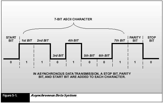
The transmission
of data occurs in either an asynchronous or synchronous
mode. In
asynchronous data transmission, each character has a start and stop bit
(Figure 5- 1). The start bit prepares the data receiver to accept the character.
The stop bit brings the data receiver back to an idle state.
Synchronous
data transmission eliminates the start and stop bits. This type
of system
uses a preamble (a known sequence of bits, sent at the start of a
message,
that the receiver uses to synchronize to its internal clock) to alert the
data receiver that a message is coming. Asynchronous systems eliminate
the need for complex synchronization circuits, but at the cost of higher
overhead than synchronous systems. The stop and start bits increase the
length of a character by 25 percent, from 8 to 10 bits.
Radio Modems
Radios cannot
transmit data directly. Data digital voltage levels must be
converted
to radio signals, using a device called a modulator, which applies the
audio to the transmitter. Conversely, at the receiver, a demodulator converts
audio back to digital voltage levels. The Harris radios are equipped with
built- in high- speed modems (the MOdulator and the DEModulator packaged
together), which permit the radios to operate with either voice or data
inputs.
Radio modems
fall into three basic categories: (1) modems with slow- speed
frequency
shift keying (FSK); (2) high- speed parallel tone modems; and (3)
high- speed
serial (single) tone modems.
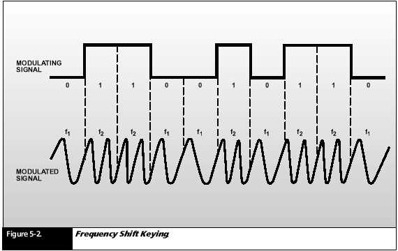
The simplest
modems employ FSK to encode binary data (0s and 1s) (see
Figure 5-
2). The input to the modulator is a digital signal that takes one
of two possible
voltage levels. The output of the modulator is an RF signal
that is one
of two possible tones. FSK systems are limited to data rates
less than
75 bps due to the effects of multipath propagation.
Amplitude
Shift Keying (ASK) is similar to FSK except that it is the amplitude of
the carrier that is modulated rather than the frequency.
Higher rates
are possible with more modern Phase Shift Keying (PSK)
modulation
methods and advanced coding schemes. PSK is described
later in
this chapter.
Error Control
There are several different approaches to avoid data transmission problems.
Forward Error
Correction (FEC) adds redundant data to the data stream
to allow
the data receiver to detect and correct errors. An important
aspect of
this concept is that it does not require a return channel for
the acknowledgment.
If a data receiver detects an error, it simply corrects
it and accurately
reproduces the original data without notifying the data
sender that
there was a problem. Downsides of FEC: Unlike ARQ, FEC does not ensure
error- free data transmission; FEC decreases the effective data throughput.
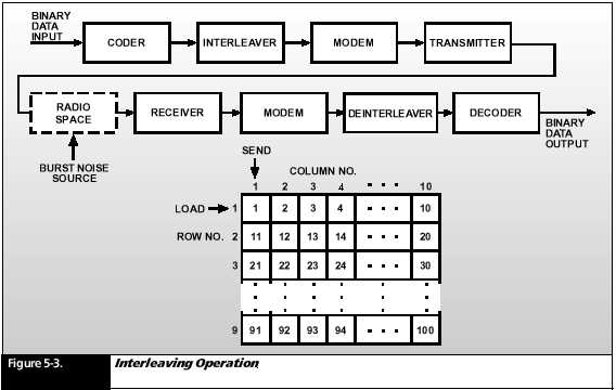
The FEC coding
technique is most effective if errors occur randomly in a
data stream.
The radio medium, however, typically introduces errors that occur in bursts
that is, intervals with a high bit error ratio (BER) in the channel are
interspersed with intervals of a low BER. To take full advantage of the
FEC coding technique, its best to randomize the errors that occur in the
channel by a process called interleaving (Figure 5- 3).
For example, at the modulator, the data stream enters a 9- row by 10- column matrix. The blocks are entered by rows and unloaded by columns. When the data stream leaves the matrix for transmission, the sequence of output bits will be 1, 11, 21, and so on.
At the demodulator,
de- interleaving reverses the process. Data is entered
by columns
in a matrix identical to that at the transmitter. It is read out in rows,
restoring the sequence of data to its original state. Thus, if a burst
were to cause 9 consecutive bits to be in error, no more than 3 of them
will fall in any 30- bit sequence of bits after de- interleaving.
Then, if an
FEC coding technique were used, the errors would be corrected.
Soft- decision
decoding further enhances the power of the error- correction
coding. In
this process, a group of detected symbols that retain their
analog character
are compared against the set of possible transmitted
code words.
The system remembers the voltage from the detector and applies a weighing
factor to each symbol in the code word before making a decision about which
code word was transmitted.
Vocoder
Data communications
techniques are also used for encrypting voice calls
by a device
called a vocoder (short for voice coder- decoder). The vocoder
converts
sound into a data stream for transmission over an HF radio channel. A vocoder
at the receiving end reconstructs the data into
telephone-
quality sound.
Channel Equalization and Excision Filtering
In addition
to error correction techniques, high- speed serial modems may
include two
signal- processing schemes that improve data transmissions.
An automatic
channel equalizer compensates for variations in the channel
characteristics
as data is being received. An adaptive excision filter seeks out and suppresses
narrowband interference in the demodulator input,
reducing
the effects of co- channel interference, that is, interference on the same
channel that is being used. Harris has patented several techniques
to perform
these functions.
Modern High Data Rate Modem Waveforms
High- speed
modem technology, permits data rates as high as 64 kbps. Radio transmission
paths have varying characteristics depending upon the frequency band (HF,
VHF, and UHF) and the bandwidth of the channel.
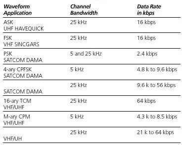
Although
most HF channels are bandwidth limited to 3 kHz; VHF, UHF, and
SATCOM channels
have both 5 kHz and 25 kHz bandwidths. To accommodate and maximize the
data throughput rate for these radio transmission types, a number of robust
data waveforms have been created. Table 5-1 lists these different waveform
types and their applications.
Phase Shift Keying (PSK)
PSK is similar to FSK, shown in Figure 5- 2, except that it is the phase of the carrier rather than the frequency that is modulated.
Binary Phase Shift Keying (BPSK)
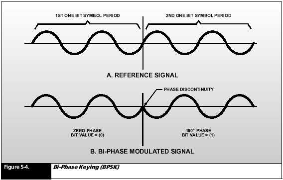
The simplest
form of PSK is called Binary Phase Shift Keying (BPSK) shown
in Figure
5- 4. Figure 5- 4a shows a reference wave covering two bit periods. Figure
5- 4b shows the wave after modulation with a (0) bit and a (1) bit. Notice
that the signal corresponding to the second bit (1) is an upside-down version
of the reference waveform. This portion of the signal is 180° with
respect to the reference waveform.
Notice also
that the transition from the first bit to the second is abrupt. This sudden
phase discontinuity creates a burst of noise sidebands referred to as splatter.
This noise causes inter- symbol interference which severely limits the
data rate that this simple form of PSK can deliver.
M- ary PSK
There are many forms of PSK. BPSK is modulated with just two phases of
the carrier. Another term for BPSK is 2- ary PSK. In this case M= 2.
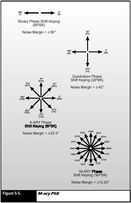
Figure 5-
5 shows a diagram that represents M- ary PSK by showing vectors that represent
the phase angles associated with the most common types of
M- ary PSK
modulation. BPSK is represented by two arrows facing away from each other
at a 180° angle. Each of the two phases of BPSK can represent only
one bit of information, either a (0) or a (1).
Quadrature
Phase Shift Keying (QPSK), or 4- ary PSK, is shown with four
arrows arranged
around a circle so that each is 45° apart. Since there are
four phase
states used in this modulation, each of these phases can
represent
two bits of information. Going clockwise around the circle,
these bits
are (00), (01), (10), and (11). This multi- bit representation per phase
is the key to faster data rates, because each phase represents
two bits
rather than just one. The figure also shows 8- ary PSK modulation, in which
each phase represents three bits. Finally, 16- ary PSK is shown. Each phase
represents four bits of information. On a non- noisy radio channel, 16-
ary PSK has a data rate that is four times faster than BPSK because each
modulation phase state represents four times as many bits.
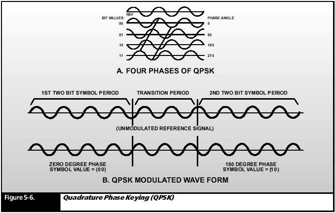
Continuous Phase QPSK
Figure 5-
6a shows what the waveforms of QPSK look like for each of the
four possible
modulation states of (00), (10), (10), and (11). Each of these bit pairs
represents a code symbol.
Figure 5-
6b shows a QPSK waveform covering two symbol periods in which
the symbols
change from (00) to (10). Notice that although this requires
an 180°
shift, there is no sudden discontinuity in the waveform. This is
because a
transition period equal to half of the symbol period has been
taken to
gradually change the phase. Although this slows down the data
rate, the
extra time is made up by the decrease in discontinuity noise
(splatter)
and attendant inter symbol interference.
Noise Margin
The problem
with PSK waveforms with M = to 8 or 16 is that the difference
in phase
between each modulation state is very small. For example, in 8- ary and
16- ary PSK, the phase difference between the (0000) and (0001)
symbols is
only 45° and 22.5°, respectively. The noise margin is only half
of those
values because any noise that would make the signal appear to be
half way
between the true values would yield a doubtful decision. Thus the
noise margin
for 8- ary and 16- ary PSK is only 22.5° and 12.5°, respectively.
In a noisy
radio channel, such a narrow phase difference is much harder to
detect than
the 90° noise margin of the two possible phase states in BPSK for the
symbols (0) and (1). So, although 16- ary PSK can be four times as fast
as BPSK in a perfect channel, it may be totally unreadable in a noisy channel.
The phase
difference between adjacent phase states in a PSK scheme is
called its
noise margin. The greater this noise margin, the more immune
to noise
this symbol transition is.
BPSK may be slow, but it is very robust in a noisy channel.
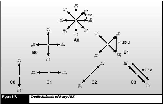
Trellis Coded Modulation (TCM)
Figure 5-
7 (A0) is a representation of an 8- ary PSK phase diagram where the linear
distance between the arrows of adjacent phase points is labeled (d). As
mentioned above, the noise margin corresponding to this distance is
22.5°.
The term distance is another way of referring to noise margin.
The distance between successive symbols in a data stream can be maximized by partitioning into code subsets having increasing distance between their elements. Starting from 8- PSK constellation (in Figure 5- 7 A0), we can create two 4- PSK subsets by taking every other signal point on the circle and putting them in one set and the rest of the signal points into another set (sets B0 and B1). The distance between adjacent phases on each of these sets is 1.85 times (d).
Each of the
resulting 4- PSK sets can be further partitioned into two
BPSK subsets
(C0, C1, and C2, C3). The distance between the two signal
points in
each BPSK subset is 2.6 times (d). Considering all combinations
of phases
for each constellation, there are a total of six subsets of the
basic 8-
PSK signal set.
Each choice
of subset, including the choice of one of the BPSK symbols
in the last
set, is assigned a bit value for a total of three bits. Because
each bit
has a different signal distance associated with it, each bit has
a different
likelihood of error.
The bits with
the highest likelihood of error are coded into subsets with a
greater distance
between bits. The effect of coding is to make the signal
different
over multiple symbols due to the bit input at the present symbol.
Distance
is now measured over the several symbol intervals allowing the
signal to
build up more distance for any bit decision.
This process
of subset partitioning and coding is called Trellis Coded
Modulation.
This basic concept can be extended to a 16- ary PSK signal
with a bit
rate of up to 64 kbps in a 25 kHz bandwidth radio channel.
SUMMARY
The transmission
of data requires the use of modems to convert digital
data RF signal
form when transmitting, and convert the RF signal back
to digital
form when receiving.
Radio modems
are classified as slow- speed FSK, high- speed parallel
tone, or
high- speed serial tone.
Serial tone
modems provide vastly improved data communications,
including
a higher data rate with powerful forward error correction
(FEC), greater
robustness, and reduced sensitivity to interference.
FEC systems
provide error correction without the need for a return link.
Interleaving
is a technique; mostly used for HF channels that
randomizes
error bursts, allowing FEC systems to work more effectively.
Soft- decision
decoding further reduces bit error rates by comparing a
group of
symbols that retain their analog character against the set of
possible
transmitted code words.
A vocoder
converts voice signals into digital data for coded
transmission
over HF channels.
Automatic
channel equalization and adaptive excision filtering are
signal processing
techniques that improve data communications
performance.
M- ary Phase
Shift Keying is a method of increasing the data rate of
radio transmissions.
M refers to the number of phases used in the
modulation
scheme.
Trellis Coded
Modulation (TCM) is a coding technique that provides
maximum data
rate capability to PSK data streams by improving the
noise margin.