Now that you have an overview of how radio waves propagate, lets take a look at how they are generated. The primary components in a VHF or UHF radio system fall into three groups: transmitters, receivers, and antennas. In most modern radio tactical sets, the transmitter and receiver are contained in a single unit called a transceiver.
This chapter presents an overview of these radio system elements.
The Anatomy of a Multiband VHF/ UHF Transceiver
In times past,
a tactical transceiver was restricted to a single band. That
is to say
that a separate radio was required for HF, VHF, and UHF service.
With the
increased requirement for greater troop mobility there is
enormous
pressure to compress all of these separate radios into a single
multiband
radio. Thanks to electronics miniaturization; multiband,
multimode
radio systems are a reality.
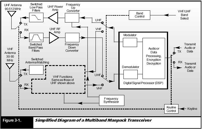
Currently, transceivers capable of VHF, UHF, and Tactical Satellite (TACSAT) service are common. A combined HF/ VHF/ UHF and TACSAT transceiver is the latest innovation in this area. The simplest transceiver must generate a modulated signal to the antenna and to receive a signal from an antenna, demodulate it, and feed the information to a headset, computer, or some other human or machine interface. A multiband transceiver must perform these functions for each of its frequency bands (Figure 3- 1).
Most functions
of the multiband transceiver are common to all frequency
bands; however,
the electronic means to accomplish these functions
differ depending
upon the operating frequency band. Thus those functions that are associated
with VHF transmit and receive frequencies must be grouped separately from
those that perform that function for the UHF band. That is why most of
the RF portions of the transceiver must be duplicated for each band, as
shown in Figure 3- 1.
Transmit Path Begins with the Digital Signal Processor
The transmitted
voice or data information is applied to a common block
in a multiband
transceiver called the Digital Signal Processor (DSP). The
DSP is actually
a powerful but miniature computer that turns the input
information
into a digital form that is manipulated within the computer.
The functions
performed by the DSP include audio bandwidth filtering,
voice digitization,
encryption, and modulation. The output of the DSP is
actually
a Low Frequency (LF) modulated carrier that is an exact replica of
what is to
be transmitted, except for its frequency. This signal is referred to as
being at an Intermediate Frequency (IF).
UHF Frequency Up- Conversion, and Frequency Synthesizer
If a UHF frequency
is selected, the IF signal at the output of the DSP is
applied to
the UHF up- converter circuits. Another block of circuits, called a frequency
synthesizer creates the various signals that are required by the up- converter
to create the desired UHF output frequency.
Power Amplifier and Transmit Filters
The up- converted
signal is then applied to a wideband power amplifier
which covers
the entire transmit band selected. In this case it is the UHF
band and
the amplifier that handles signals from 90 to 512 MHz. The signal power
output of this amplifier is typically operator selected from 1 to 10 watts.
Following
the power amplifier is a group of switched low pass filters that
clean up
its output. These remove noise, spurious signals, and harmonics
generated
by other transmitter circuits including frequency harmonics
generated
by the power amplifier. This process reduces interference with
adjacent
communications channels.
UHF Antenna Port
The output
of the UHF low pass filters is applied through a Transmit/
Receive (TX/
RX) switch (shown in Figure 3- 1 in the TX position) to the
UHF antenna
port of the transceiver. UHF antennas have a 50- ohm
input impedance.
Receive Path Begins with Switched Bandpass Filters
A receive
UHF signal is applied by the antenna to the antenna port, and
then through
the TX/ RX switch to a group of switched bandpass filters.
The purpose
of these filters is to remove signals above and below the
desired signal.
RF Amplifiers and Down- Converter
The filtered
input signals are applied to several radio frequency amplifier
stages (shown
as one block in Figure 3- 1). The typical input signal has a
signal strength
in the micro- watt range (one millionth of a watt). The RF
amplifiers
boost this signal to the milli- watt range for further processing.
The next step
in this process is to down- convert the signal to the LF IF
frequency
used by the DSP block. Again, this is accomplished by the
down- converter
in conjunction with signals from the synthesizer. In
modern radios,
this process is performed in several separate amplification
and down
conversion steps. It is shown in Figure 3- 1 as occurring in
just one
step for simplicity.
DSP Demodulation and Decryption
The final
steps in the receive process are performed by the DSP. Here
the IF signals
from the down- converter is demodulated and decrypted to
form the
base band signals (audio or data) that are used by the operator.
VHF Band
Portion of the Transceiver
The VHF transmit
and receive functions are similar to those of the UHF
band except
that they are performed by the VHF portions of the radio.
However there
is one additional function required in the VHF band and
that is antenna
matching.
VHF Whip Antenna Matching
The whip antenna frequently used with a VHF manpack radio does not present a 50- ohm impedance to the radio over the 30 to 90 MHz band. In order to maximize the power radiated from this type of antenna, a series of switched matching circuits are used in the transmit path following the switched low pass filters. The correct matching network is selected automatically by the frequency selector switch on the transceiver front panel.
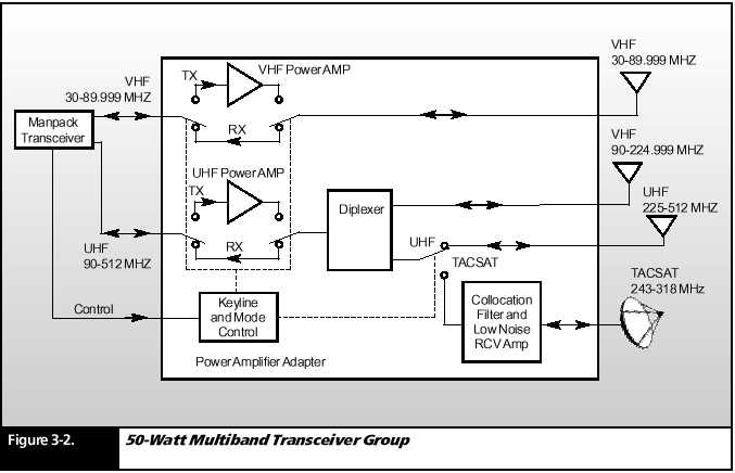
50- Watt Multiband Transceiver Group
It is common
for radios used in vehicles and in fixed stations to require
higher power
than the tactical manpack transceiver can deliver on its own.
In these
applications, the manpack transceiver is attached to a mounting
base that
includes power amplifiers and some additional antenna ports
(Figure 3-
2).
Power Amplifiers
A multiband
vehicular adapter is likely to have two or more power amplifiers that are
tailored to the frequency ports of the manpack
transceiver.
Figure 3- 2 shows a vehicular adapter with both VHF and UHF
transceiver
ports. Each of these ports is associated with a power amplifier
that is capable
of producing 50 watts of output power.
Each of these
amplifiers has a receive bypass path which is selected by the
transceiver
keyline. In the key- down transmit condition, the bypass is open and the
signal is applied to the power amplifiers. However, in the receive condition,
the amplifiers are bypassed so that the signal from the antenna ports can
pass back to the receiver circuits in the manpack transceiver.
VHF Low, VHF High, UHF, and TACSAT Antenna Ports
Most multiband
transceivers have two antenna ports, one for VHF and
the other
for UHF. In vehicular and fixed station installations it is common to have
antennas that are larger and more efficient than those used with a manpack
alone. It is therefore, convenient to have four antenna ports.
The first
port is used for low band VHF over the 30 to 89.999 MHz range.
But the UHF
path is spread between three separate antenna ports, as
shown in
Figure 3- 2.
The output
of the UHF amplifier is applied to a diplexer, which splits the UHF port
into two frequency ranges, 90 to 224.999 MHz and 225 to 512 MHz.
Each of these
frequency outputs is applied to a corresponding antenna port.
The 225 to
512 MHz path is further divided by a relay switch into a UHF
path and
a TACSAT path. This is because the TACSAT path requires a
collocation
filter, a Low Noise Receive Amplifier (LNA), and a separate
antenna port.
This additional filtering and amplification on the TACSAT
path is useful
because of the typically low level of received signal from the tactical
satellite in orbit 22,300 miles above the equator. The collocation filter
is there to remove radio noise generated by vehicle ignition, motors, and
other transmitters that would otherwise obscure the faint signals from
the satellite.
The Antenna Group
The antenna
is one of the most critical elements in a radio circuit. Here,
we will look
at typical antenna types and their applications.
Antenna Characteristics and Parameters
Some of the most commonly used terms describe antennas are impedance, gain, radiation pattern, take- offto angle, and polarization. Every antenna has an input impedance that represents the load to be applied to the transmitter. This impedance depends upon many factors such as antenna design, frequency of operation, and location of the antenna with respect to surrounding objects.
The basic
challenge in radio communications is finding ways to get the
most power
possible, where and when you need it, to generate and
transmit
signals. Most transmitters are designed to provide maximum
output power
and efficiency into a 50- ohm load. (Ohm is a unit of
measurement
of resistance.) Some antennas, such as log periodic
antennas,
can provide a 50- ohm load to the transmitter over a wide
range of
frequencies. These antennas can generally be connected
directly
to the transmitter. Other antennas, such as dipoles, whips, and
long- wire
antennas, have impedances that vary widely with frequency
and the surrounding
environment.
HF applications
use an antenna tuner or coupler. This device is inserted
between the
transmitter and antenna to modify the characteristics of
the load
presented to the transmitter so that maximum power may be
transferred
from the transmitter to the antenna.
For most VHF
and UHF applications, the antennas have built- in broadband-
matching
units so separate antenna coupler units are generally not required.
Antenna Gain and Radiation Pattern
The gain of an antenna is a measure of its directivity its ability to focus the energy it radiates in a particular direction. The gain may be determined by comparing the level of signal received from it against the level that would be received from an isotropic antenna, which radiates equally in all directions. Gain can be expressed in dBi; the higher this number, the greater the directivity of the antenna. Transmitting antenna gain directly affects transmitter power requirements. If, for example, an omnidirectional antenna were replaced by a directional antenna with a gain of 10 dBi, a 100- watt transmitter would produce the same effective radiated power as a 1- kW transmitter and omnidirectional antenna.
In addition
to gain, radio users must understand the radiation pattern of
an antenna
for optimal signal transmission. Radiation pattern is deter-
mined by
an antennas design and is strongly influenced by its location
with respect
to the ground. It may also be affected by its proximity to
nearby objects
such as buildings and trees. In most antennas, the pattern
is not uniform,
but is characterized by lobes (areas of strong radiation) and nulls (areas
of weak radiation). These patterns are generally represented graphically
in terms of plots in the vertical and horizontal planes (Figure 3- 3),
which show antenna gain as a function of elevation angle (vertical pattern)
and azimuth angle (horizontal plot). The radiation patterns are frequency
dependent, so plots at different frequencies are required to fully characterize
the radiation pattern of an antenna.
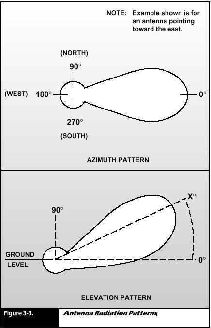
In determining
communications range, it is important to factor in the
take- off
angle, which is the angle between the main lobe of an antenna
pattern and
the horizontal plane of the transmitting antenna. For VHF
and UHF applications,
low take- off angles are generally used for LOS
communications;
high take- off angles are used for ground- to- air, close
air support.
The orientation
of an antenna with respect to the ground determines its
polarization.
Most VHF and UHF whips and center fed monopole antennas
are vertically
polarized.
A vertically
polarized antenna produces low take- off angles. The main
drawback
of vertical whip antennas is their sensitivity to ground
conductivity
and locally generated noise. Center fed monopoles avoid the
sensitivity
to ground conductivity and are preferred for vehicular mounts.
Horizontally
polarized antennas, such as a 1/ 2- wave dipole, have high
elevation
angles. This type of antenna is particularly useful when the
transmitter
is near a forest or jungle. This allows the radiation to get
above the
trees rather than having them absorbed. Diffraction at the
treetops
tends to bend the radiation down so that it follows the treetops.
For best
results, the transmitting and receiving antennas should have
the same
polarization.
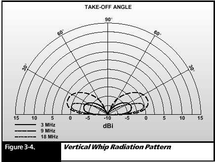
VHF Antennas
There are
a countless variety of antennas used in VHF communication.
Well focus
here on some of the more common types. The vertical whip antenna is frequently
used since it is omnidirectional and has low take- off angles. It is vertically
polarized. A typical vertical whip
radiation
pattern is shown in Figure 3- 4. A reflector, consisting of a second vertical
whip, can add directivity to the radiation pattern of a whip.
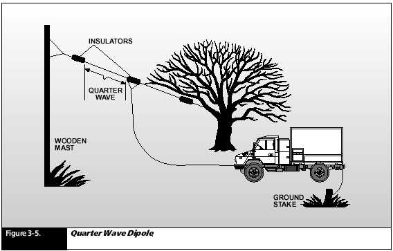
Another useful
type of antenna is the center fed 1/ 4 wave dipole, which
is basically
two lengths of wire fed at the center (Figure 3- 5). This is a
horizontally
polarized antenna and is frequently used for vehicular and
fixed station
applications.
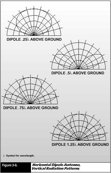
The radiation
pattern can change dramatically as a function of its distance
above the
ground. Figure 3- 6 shows the vertical radiation pattern of a
horizontal
dipole for several values of its height (in terms of transmitting wavelength)
above the ground.
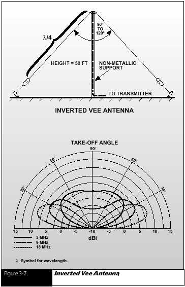
An inverted
vee (sometimes called a drooping dipole) produces a
combination
of horizontal and vertical radiation with omnidirectional
coverage.
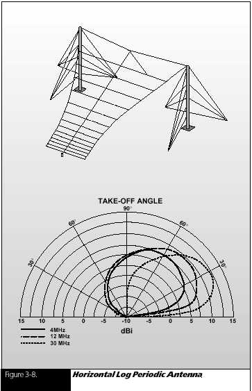
See Figure 3- 7. For fixed station use on high elevations (high hills or
mountain tops) a log periodic directional antenna can be used for very
long LOS communications of 100 miles or more. See Figure 3.8
UHF and SATCOM Antennas
For most UHF
manpack applications, the transceiver is mounted with a
short, stubby
antenna that resembles a hot dog in shape. This antenna
is used for
relatively short LOS distances and its virtue is its small size.
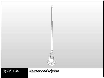
For vehicular or shelter mounted applications, an effective general- purpose UHF antenna is a center- fed dipole (Figure 3- 9a). This antenna looks like a thick whip antenna. It is constructed within a fiberglass tube and consists of a dipole mounted vertically within the tube along with its feed point. Its significant virtue is that it is relatively independent of the ground quality. It has a low take off angle, and it is vertically polarized. The center-fed dipole antenna has a pattern similar to the whip pattern shown in Figure 3- 4.
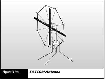
There are center- fed dipoles designed for VHF frequencies as well. The UHF Tactical Satellite (TACSAT) antenna has a unique inverted umbrella shape (Figure 3- 9b). It produces a directed beam that must be pointed directly at the satellite in order to be effective.
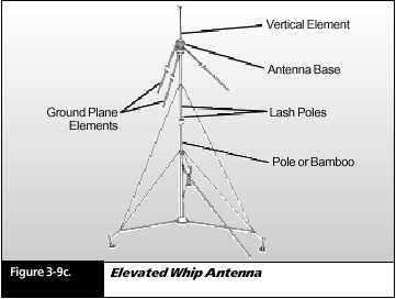
For fixed
station use, an elevated whip or center- fed dipole greatly
increases
the LOS range (Figure 3- 9c). This antenna assembly consists of
a mast and
a vertical whip or dipole mounted above ground plane rods.
Again, this
antenna structure can be used for both VHF and UHF applica-
tions with
the proper selection of antenna and ground plane rod lengths.
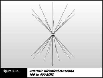
Another popular
UHF antenna used for fixed station use is the Biconical
Antenna shown
in Figure 3- 9d. An antenna of this type has been designed
to cover
the 100 to 400 MHz range. Its broadband capability makes it an
excellent
choice for wide band Transmission Security (TRANSEC) modes such
as frequency
hopping. Refer to Chapter 7 for a discussion of TRANSEC.
The Biconical
Antenna is usually mounted on a mast similar to the one
shown in
Figure 3- 9c.
SUMMARY
A radio system consists of a transceiver and an antenna group.
The transceiver provides both transmitting and receiving functions.
The transmit
function consists of modulation, carrier generation
frequency
translation, and power amplification.
The receive
function consists of RF signal filtering, amplification,
frequency
down conversion, and demodulation.
Antenna selection
is critical to successful VHF, UHF, and TACSAT
communications.
Antenna types include vertical whips, center- fed
dipoles,
biconical antennas, directional log periodic arrays, and
umbrella
TACSAT antennas.
An antenna
coupler matches the impedance of the antenna to that
of the transmitter,
transferring maximum power to the antenna.
The gain of
an antenna is a measure of its directivity its ability
to focus
the energy it radiates in a particular direction.
Antenna radiation
patterns are characterized by nulls (areas of
weak radiation)
and lobes (areas of strong radiation).