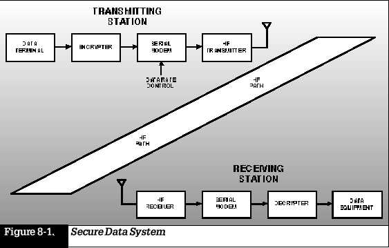
Secure Data System
HF radio offers
a unique combination of cost effectiveness and versatility for long-haul
communications. In recent years, computer technology and high-speed digital
signal processing have enhanced the performance and reliability of HF communications
systems, resulting in reduced operator involve-ment in establishing HF
communications circuits. At the same time, new technology has dramatically
reduced the size and weight of HF radio equipment. Diverse capabilities,
which formerly required separate pieces of equipment, are now combined
and embedded into the radio transceiver itself.
Examples
of HF Communications Systems Harris Corporation, RF Communications Division,
designs, manufactures, and installs turnkey radio communications
systems for
worldwide government, military, and commercial markets. Here are some examples
of how these HF systems come together in a modern communications network
to meet complex communications needs.
Secure Data
System
Figure 8-1
shows a typical secure HF data transmission system, which can be used whenever
it is necessary to transfer data securely between two points. The serial
modem, which uses FEC coding, also provides real-time channel equalization
and data interleaving for protection against fading, and automatic excision
filters remove interference from up to four sources. The transmit modem
data rate adjusts to the terminal data rate and is selected
on the basis
of an LQA (estimate of channel quality). The amount of coding (redundancy)
used in the FEC varies as a function of the selected modem data rate. Thus,
if poor channel quality is predicted, a relatively low data rate and a
more powerful FEC code will be designated.
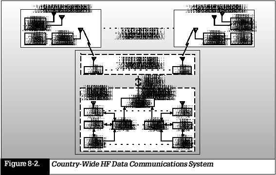
Country-Wide
HF Data Communications System
A country-wide
HF data communications system, which provides economical, long-range communications,
is shown in Figure 8-2. The HF data communications system links a fixed
central communications center and 12 subordinate stations located throughout
the country. The system incorporates an ALE capability that offers fully
automatic operation with unattended processing of incoming messages. Each
subordinate station has additional HF and VHF radios that provide voice
and data communications to mobile stations in its vicinity. In the data
communications mode, an ARQ message protocol is used for error detection
and correction. The central
station is
a fixed installation with separate transmit and receive control sites.
Intersite communications and control are via microwave or a landline link.
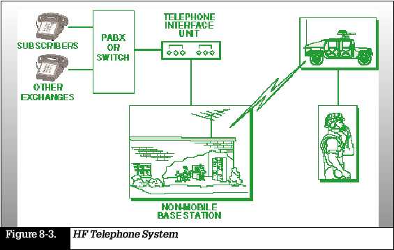
HF Telephone
System
An HF radio
link can extend the reach of a telephone network, as shown in Figure 8-3.
The system operates much like the cord-less telephone widely used in homes
today, but covers hundreds of thousands of miles using HF radio. The HF
telephone system enables users to place calls to and from mobile radio
transceivers into the commercial switched telephone network or private
subscriber telephone lines. Calls from the field can be placed over HF,
VHF, or UHF to anywhere in the world through the base station telephone
switch or exchange. To initiate a call, the user enters a telephone number
just as if the Remote Access Unit (RAU ) were a telephone set connected
directly to the base station telephone exchange. At this point, the number
dialed is transmitted through the RAU to the Telephone Interface Unit (TIU).
As the TIU dials the digits and the telephone rings, call progress tones
are heard by the mobile operator. In order to contact anyone in the field,
a telephone user dials a telephone number (or the extension) to
which the
TIU is connected from anywhere in the world. The call is automatically
answered by the TIU and the user is connected directly with the field radio.
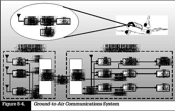
Ground-to-Air
Communications System
Figure 8-4
is a block diagram of a ground-to-air communica-tions system with a split-site
ground station capable of simulta-neous data, facsimile, or voice communications
with up to four airborne platforms. This system dedicates one ground-based
receiver-transmitter pair and an associated controller to ALE. Once a ground-air
link is established, the station controller hands off the traffic channel
to another receiver-transmitter pair. This system also incorporates the
cordless telephone capability
described
above. Thus, an airborne platform has access to the telephone network.
Each aircraft incorporates an HF transceiver with built-in ALE controller
and data modem, plus a 400-watt solid-state power amplifier and antenna
coupler. Intersite communications between receiver and transmitter sites
are via radio or landline.
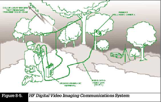
HF Digital
Video Imaging Communications System
This system
captures, digitizes, and transmits video images in near real time from
a mobile unit to a base station via an HF data link. Figure 8-5 shows a
scenario in which an unattended still-video camera sends images to an imaging
terminal via a fiber-optic link. The terminal captures and digitizes the
image and sends the data to a modem in the transceiver, which relays the
data to the base. Communications may be via a two-way link
that uses
an ARQ protocol to obtain error-free transmission of the image, or a one-way
link in which FEC coding reduces the probability of error in the received
message.
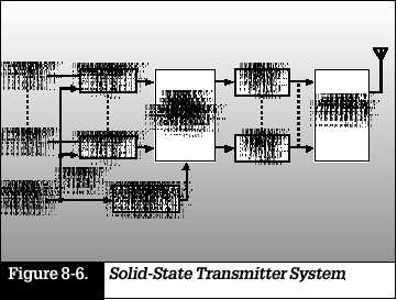
Broadband
Transmitter System
The biggest
HF communication problem that must be solved on board large naval ships
is how to run multiple HF transmit and receive circuits simultaneously
without interfering with each other, and that all circuits operate through
a very few number of antennas (due to size and space limitations). Harris
has developed the optimum solution to these problems with its ultra-linear
broadband transmitting system. Harris system also
supports
rapid frequency changes through use of ALE and frequency hopping. Figure
8-6 is a simplified block diagram of a solid-state transmitter system capable
of delivering up to 4 kW in the 2- to 30-MHz frequency range into an antenna.
Signals from up to eight independent audio sources modulate HF exciters.
The outputs of the exciter route through a signal distribution unit into
a bank of linear solid-state power amplifiers, each capable of delivering
500 watts. The signal distribution unit allows various combinations of
exciter signals to be applied to the power ampli-
fiers, so
that, for example, the signal from a single exciter may be
applied to
all eight amplifiers. The amplifier outputs are added in a passive power
combiner and supplied to an antenna.
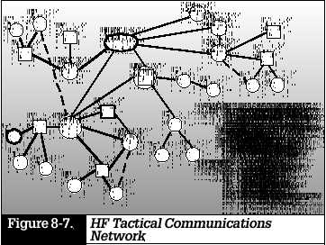
HF Tactical
Communications Network
Figure 8-7 shows a portion of a tactical communications network that provides coverage over distances ranging from less than 50 miles to more than 1,500 miles. In a network of this type, the individual elements include frequency hopping, encryption, and ALE capabilities. Network requirements dictate that links are provided between the fixed headquarters site and fixed installations for quasi-permanent military regions and zones. Provisions are made for communications between headquarters and task forces at fixed, non-permanent installations. Lower echelon communications have a combination of fixed, mobile, and man-portable equipment. Frequency management of the network is a headquarters responsibility.
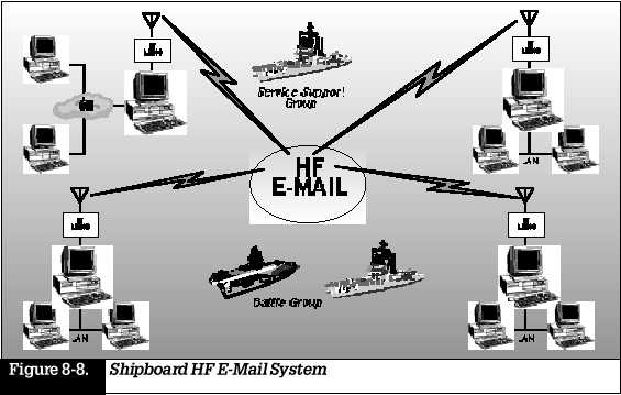
HF E-Mail and Inter-Networking
Electronic mail and other inter-networking technologies are becoming increasingly important for interoffice communications. However, many users find that communications between remote stations are difficult and/or expensive, due to costly telephone or satellite charges. Harris HF radios and systems are an excellent alternative for providing these services to distant users or stations. Typical applications include:
Naval ship-to-shore
and ship-to-ship communications.
Embassy
Ministry of Foreign Affairs communications.
Oil/Gas/Mining
operations.
In the following
discussion, we will focus on naval applica-tions; similar configurations
support other HF E-mail and inter-networking communications system requirements.
An HF E-mail system for naval ships and deployed forces that supports naval
communications, including administrative, logistic, and engineering order-wire
traffic, is shown in Figure 8-8.
A typical
shipboard HF E-mail system consists of a Harris RF-6750 Wireless Gateway,
an RF-7210 ALE Controller, an RF-5710 High-Speed HF Modem, and connection
to a Harris HF radio system (the RF-590A Receiver and RF-1140 Transmitter).
The modem and radio system are remotely controlled and
managed by
the Wireless Gateway computer. The RF-6750 Wireless Gateway provides seamless
data trans-fers between common networked applications, such as E-mail and
FTP file transfer, running on geographically separated Local Area Networks
(LANs). This system also supports the applica-tion
of sending
mobile HF data messages over the Internet. The data transfers are accomplished
automatically using HF radio. Unlike conventional network routers and gateways,
the RF-6750 is designed specifically to operate over HF radio circuits.
System Design Considerations
Harris RF Communications Division has a communications systems engineering department staffed by engineers who are specialists in the design of custom equipment for the one-of-a-kind type of application. The following are some of the factors that we consider in designing a modern HF radio system.
System definition
Who are
the users?
What is
their location?
Are communications
one-way or two-way?
What are
the interfaces with other communications media?
What is
the operating environment (hostile or friendly, rural or urban)?
Transfer of information
What type
of traffic is there (voice, data, images)?
Do the
priority levels differ, depending on the message source and/or content?
What are
the security levels for safeguarding the information?
Message protection and security
What is
the correct type of error detection and correction for data?
What type
of COMSEC is needed?
Will spread-spectrum
or frequency-hopping techniques be used to avoid interception or jamming?
Is excision
filtering needed to remove interfering signals?
System availability
What is
the probability of transferring messages in real time?
Can alternate
routing be used to enhance message availability?
Can lower
priority traffic use store-and-forward techniques?
Are there
any operational restrictions due to propagation, transmitter power, or
other constraints?
Traffic analysis
What are
the typical message lengths?
What is
the average number of messages per unit of time?
What are
the message priorities?
When is
the peak traffic?
What are
the types of traffic?
Projected
growth for each category of traffic
What impact
do higher traffic levels have on system implementation?
Are additional
nodes and/or relays necessary?
Impact on
message structure
Is the
format for data message compatible with traffic requirements?
Include
security classification, priority, source, and destination address.
Site
Is this
a fixed or mobile site?
Fixed site
Are the
receiving, transmitting, and control functions collocated or separate?
Is this
a permanent or temporary installation?
Are there
any frequency restraints for collocated receivers and transmitters?
What are
the staffing requirements?
What are
the environmental considerations?
What type
of power is available?
Is uninterrupted
power a requirement?
Mobile site
Is the equipment
designed for a vehicle, ship, shelter, or aircraft?
Are manpacks
required?
What are
the antenna limitations and constraints?
What are
the physical size constraints?
What are
the bandwidth and primary power requirements?
What are
the environmental considerations?
Communications protocol
Is there
a return channel for ARQ?
Is ALE
being used?
What are
the data protocols?
Equipment selection
Transmitter
requirements: Power output, solid state versus tube, broadband or narrowband,
allowable distortion, frequency range, tuning speed, remote control?
Receiver
requirements: Selectivity, dynamic range, distortion, remote control?
Antenna
requirements: Gain, bandwidth, polarization, radiation pattern, available
terrain, remote control?
Data communications systems
What is
the data rate?
How is
data being protected (interleaving, encryption)?
What is
the modulation scheme?
Is the
modem serial or parallel tone?
Interface to other equipment and systems
What other
equipment is required (fax, data terminal, imaging systems)?
What other
types of systems are involved?
Is there
an interface with VHF/UHF radio systems, satellite, or switched telephone
networks?
Command and control
Will operation
be attended or unattended?
Is self-test
required?
Are the
transmitter, receiver, and control sites at different places (split site)?
SUMMARY
Modern HF
radio is small and lightweight. Features and capa-bilities,
which formerly
required additional equipment, are now embedded into the radio transceiver.
HF radio
plays a key role in modern long-range telecommuni-cations systems, often
working in conjunction with other media, such as satellites, cellular networks,
and telephone landlines.
A systems
approach is needed to obtain the best results in designing a modern HF
radio communications network.