Asynchronous and Synchronous Data
From the very
beginning, HF radio used Morse code for data communications. Over time,
improved techniques were developed for data transmission that take into
account the vari-ability of the HF medium and greatly increase the speed
at which data transmission occurs over a radio link. In addition, the appli-cation
of error-correcting codes and automatic repeat request
(ARQ) techniques
offering error-free data transfer permits the use of HF radio in computer-to-computer
communications systems. To understand the principles of HF data communication,
well define some common data terminology and explain the signifi-cance
of the modem. We will also outline some of the problems and solutions associated
with HF data communication.
Binary Data
Communication as an activity involves the transfer of informa-tion from a transmitter to a receiver over a suitable channel. Consider this book, for instance. It uses symbols (the alphabet) to encode information into a set of code groups (words) for trans-mission over a channel (the printed page) to a receiver (the reader). Applying this principle to data (information), we begin by using a kind of shorthand to transform the data into code words (binary digits, or bits) for transmission over a channel (HF radio) to a receiver (the reader).
Bits are part
of a number system having a base of two that uses only the symbols 0 and
1. Thus, a bit is any variable that assumes two distinct states. For example,
a switch is open or closed, a voltage is positive or negative, and so on.
A simple way to communicate binary data is to switch a circuit off and
on in patterns that are interpreted at the other end of a link. This is
essentially what was done in the early days of telegraphy.
Later schemes
used a bit to select one of two possible states of the properties that
characterize a carrier (modulated radio wave) either frequency or amplitude.
More sophisticated approaches allow the carrier to assume more than two
states and hence to represent multiple bits.
Baud Rate
Data transmission
speed is commonly measured in bits per second (bps). Sometimes the word
baud is used synonymously with bps, although the two terms actually have
different meanings. Baud is a unit of signaling speed and is a measure
of symbols per second that are being sent. A symbol may
represent
more than one bit. The maximum baud rate that can be supported by a radio
channel depends on its bandwidth the greater the band-width,
the greater
the baud rate. The rate at which information is transmitted, the bit rate,
depends on how many bits there are per symbol.
Asynchronous
and Synchronous Data
The transmission
of data occurs in either an asynchronous or a synchronous mode, as defined
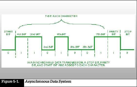
below. In asynchronous data transmission, each character has a start and
stop bit (Figure 5-1). The start bit prepares the data receiver to accept
the character. The stop bit brings the data receiver
back to an
idle state.
Synchronous data transmission eliminates the start and stop bits. This type of system typically uses a preamble (a known sequence of bits, sent at the start of a message, that the receiver uses to synchronize to its internal clock) to alert the data receiver that a message is coming.
Asynchronous systems eliminate the need for complex synchronization circuits, but at the cost of higher overhead than synchronous systems. The stop and start bits increase the length of a character by 25 percent, from 8 to 10 bits.
HF Modems
A conventional
voice radio cannot transmit data directly. Data digital voltage levels
must be converted to audio, using a device called a modulator, which applies
the audio to the transmitter. Conversely, at the receiver, a demodulator
converts audio back to digital voltage levels. Harris RF-5000 radios are
equipped with built-in high-speed modems (the MOdulator and the DEModulator,
packaged together), which permit the radios to operate with either voice
or data inputs. HF modems fall into three basic categories: (1) modems
with slow-speed frequency shift keying (FSK); (2) high-speed parallel tone
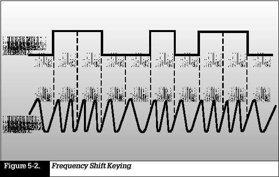
modems; and (3) high-speed serial (single) tone modems. The simplest modems
employ FSK to encode binary data (0s
and 1s) (see
Figure 5-2). The input to the modulator is a digital signal that takes
one of two possible voltage levels. The output of the modulator is an audio
signal that is one of two possible tones. HF FSK systems are limited to
data rates less than 75 bps due to the effects of multipath propagation.
Higher rates are possible with multi-tone FSK (MFSK), which uses a greater
number of frequencies. High-speed HF modem technology, using both parallel
and serial tone waveforms to allow transmission at up to 4800 bps, was
pioneered by Harris in the early 1980s. The serial tone modem carries information
on a single audio tone. This provides vastly improved data communications
on HF channels, including greater robustness, reduced sensitivity to interference,
and a higher data rate with powerful forward error correction (FEC), described
in the next section. Harris currently has its fourth generation of high-speed
modems on the market.
Error Control
Harris RF
Communications engineers use several different approaches to avoid data
transmission problems. FEC adds redundant data to the data stream to allow
the data receiver to detect and correct errors. An important aspect of
this concept is that it does not require a return channel for the acknowledgment.
If a data receiver detects an error, it simply corrects it and accurately
reproduces the original data without
notifying
the data sender that there was a problem. The FEC coding technique is most
effective if errors occur randomly in a data stream. The HF medium, however,
typically introduces errors that occur in bursts that is, intervals with
a high bit error ratio (BER) in the channel are interspersed with intervals
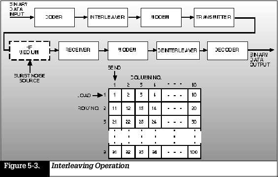
of a low BER. To take full advantage of the FEC coding technique, its
best to randomize the errors that occur in the channel by a process called
interleaving (Figure 5-3). For example, at the modulator, the data stream
enters a 9-row by 10-column matrix. The blocks are entered by rows and
unloaded by columns. When the data stream leaves the matrix for transmission,
the sequence of output bits will be 1, 11, 21, and so on. At the demodulator,
the process is reversed by de-interleaving.
Data is entered
by columns in a matrix identical to that at the transmitter. It is read
out in rows, restoring the sequence of data to its original state. Thus,
if a burst were to cause 9 consecutive bits to be in error, no more than
3 of them will fall in any 30-bit sequence of bits after de-interleaving.
Then, if an FEC coding technique were used, the errors would be corrected.
Soft-decision decoding further enhances the power of the error-correction
coding. In this process, a group of detected symbols that retain their
analog character are compared against the set of
possible
transmitted code words. The system remembers the voltage from the detector
and applies a weighing factor to each symbol in the code word before making
a decision about which code word was transmitted. Data communications techniques
are also used for encrypting voice calls by a device called a vocoder (short
for voice coder-decoder). The vocoder converts sound into a data stream
for transmission over an HF channel. A vocoder at the receiving end reconstructs
the data into telephone-quality sound. In addition to error correction
techniques, high-speed serial
modems may
include two signal processing schemes that improve data transmissions.
An automatic channel equalizer compensates for variations in the channel
characteristics as data is being received. An adaptive excision filter
seeks out and suppresses narrowband interference in the demodulator input,
reducing the effects of co-channel interference, that is, interfer-ence
on the same channel that is being used. Harris has patented
several techniques
to perform these functions.
SUMMARY
The transmission of data requires the use of modems to convert digital data into analog form when transmitting, and convert analog data back to digital form when receiving.
HF modems are classified as slow-speed FSK, high-speed parallel tone, or high-speed serial tone.
Serial tone modems provide vastly improved data communica-tions on HF channels, including a higher data rate with powerful forward error correction (FEC), greater robustness, and reduced sensitivity to interference.
FEC systems provide error correction without the need for a return link.
Interleaving is a technique that randomizes error bursts, allowing FEC systems to work more effectively.
Soft-decision decoding further reduces bit error rates by comparing a group of symbols that retain their analog char-acter against the set of possible transmitted code words.
A vocoder converts voice signals into digital data for coded transmission over HF channels.
Automatic
channel equalization and adaptive excision filtering are signal processing
techniques that improve data communi-cations performance.