Transmitter Group
Now that you
have an overview of how radio waves propagate, lets take a look at how
they are generated. The primary components in an HF radio system fall into
three groups: transmitters, receivers, and antennas. In many modern radio
sets, the transmitter and receiver are contained in a single unit called
a transceiver. In large, fixed systems, transmitting
stations
and receiving stations are customarily at separate loca-tions, often controlled
from a remote third site.
Transmitter
Group
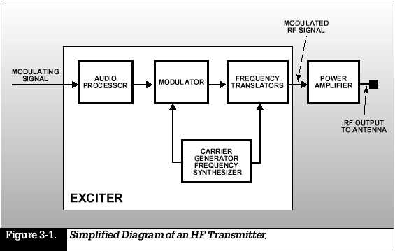
Although transmitters
may vary widely in their configuration, they all consist of an exciter
and power amplifier. A simplified diagram of a typical HF transmitter is
shown in Figure 3-1. The exciter synthesizes a carrier, which has one of
its properties amplitude, frequency, or phase modified (modulated)
by a lower frequency signal derived from a source
of information
such as a microphone. The resulting signal is converted to the frequency
that is to be transmitted. The power amplifier boosts the output power
of the signal to the desired wattage for transmission before sending it
through a cable to the transmitting antenna. The transmitter may also contain
filters that are used to clean up its output. A bandpass filter removes
noise, spurious signals, and harmonics generated in the exciter, or output
frequency harmonics coming from the power amplifier. This process reduces
interference with adjacent communications channels.
Receiver
Group
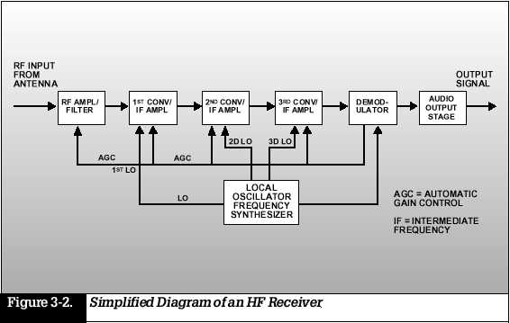
All modern
HF receiving systems include an RF input filter/amplifier, a series of
frequency converters and intermediate frequency (IF) amplifiers, a demodulator,
and a local oscillator frequency synthesizer (see Figure 3-2). To function,
the receiver selects a desired signal, amplifies it to a suitable level,
and recovers the information through the process of demodulation, in which
the original modulating signal is recovered from a
modulating
carrier. With contemporary radio equipment, many of these functions are
performed digitally. In order to filter out noise and undesired signals,
the RF input stage sometimes incorporates a tunable preselector (a bandpass
filter). The filtered signal is then amplified and converted to another
frequency for further processing. But the filtering process does not end
here. Typically, the received signal is filtered and amplified again at
several different intermediate frequencies. The amplification provided
in these stages is a variable that depends on the strength of the received
signal. In order to output voice or data, for example, the demodulator
produces an audio-frequency (baseband) signal that interfaces with additional
equipment. Also, because the strength of the
input signal
may not be constant, the demodulator stage produces a voltage proportional
to the level of the RF input signal. To compensate for changes in the signal,
the voltage is fed back to the RF and IF amplifiers for automatic gain
control (AGC), to maintain a constant input to the demodulator.
The Antenna Group
The antenna is one of the most critical elements in a radio circuit. Here, we will look at typical antenna types and their applications.
Antenna Characteristics
and Parameters
Some of the
most commonly used terms to describe antennas are impedance, gain, radiation
pattern, take-off angle, and polarization. Every antenna has an input impedance,
which represents the load to be applied to the transmitter. This impedance
depends upon many factors, such as antenna design, frequency of operation,
and location of the antenna with respect to surrounding objects. The basic
challenge in radio communications is finding ways to get the most power
possible, where and when you need it, to generate and transmit signals.
Most transmitters are designed to provide maximum output power and efficiency
into a 50-ohm load. (OHMis a unit of measurement of resistance. Its symbol
is ?.) Some antennas, such as log periodic antennas, can provide a 50-ohm
load to the transmitter over a wide range of frequencies. These antennas
can generally be connected directly to the trans-mitter. Other antennas,
such as dipoles, whips, and long-wire
antennas,
have impedances that vary widely with frequency and the surrounding environment.
In these cases, an antenna tuner or coupler is used. This device is inserted
between the transmitter and antenna to modify the characteristics of the
load presented to the transmitter so that maximum power may be transferred
from the transmitter to the antenna. The gain of an antenna is a measure
of its directivity its ability to focus the energy it radiates in a particular
direction. The gain may be determined by comparing the level of signal
received from it against the level that would be received from an isotropic
antenna, which radiates equally in all directions. Gain can be expressed
in dBi; the higher this number, the greater the directivity of the antenna.
Transmitting antenna gain directly affects transmitter power requirements.
If, for example, an omni-directional antenna were replaced by a directional
antenna with a gain of 10 dBi, a 100-watt transmitter would produce the
same effective radiated power as a 1-kW transmitter and omnidirec-tional
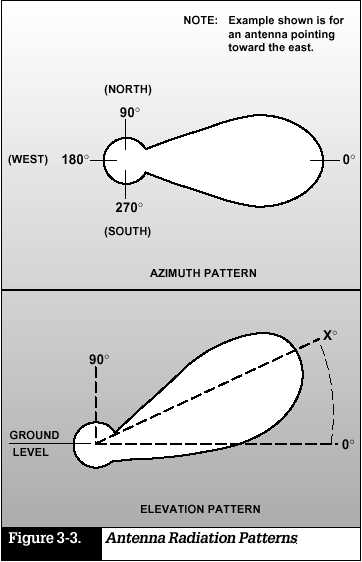
antenna. In addition to gain, radio users must understand the radiation
pattern of an antenna for optimal signal transmission. Radiation pattern
is determined by an antennas design and is strongly influenced by its
location with respect to the ground. It may also be affected by its proximity
to nearby objects such as buildings and trees. In most antennas, the pattern
is not uniform, but is characterized by lobes (areas of strong radiation)
and nulls (areas
of weak radiation).
These patterns are generally represented graphically in terms of plots
in the vertical and horizontal planes (Figure 3-3), which show antenna
gain as a function of elevation angle (vertical pattern) and azimuth angle
(horizontal plot). The radiation patterns are frequency dependent, so plots
at different frequencies are required to fully characterize the radiation
pattern of an antenna. In determining communications range, it is important
to factor in the take-off angle, which is the angle between the main lobe
of an antenna pattern and the horizontal plane of the transmitting antenna.
Low take-off angles are generally used for long-haul communications; high
take-off angles are used for shorter-range communications. The orientation
of an antenna with respect to the ground deter-mines its polarization.
Most HF antennas are either vertically or horizontally polarized. A vertically
polarized antenna produces low take-off angles and is therefore suitable
for ground waves
and for long-haul
sky wave links. The main drawback of vertical antennas is their sensitivity
to ground conductivity and locally generated noise. It is necessary to
use a grounding screen to get the best results. A horizontally polarized
antenna radiates at higher take-off angles and is suitable for shorter
range communications, out to about 400 miles. By adjusting the height of
the antenna above ground, it is possible to increase gain at lower take-off
angles for longer-range sky wave performance. Horizontally polarized antennas
are largely independent of ground conductivity, and
are less
affected by local noise than vertical antennas. For ground wave propagation,
the transmitting and receiving antennas should have the same polarization
for best results. For sky wave propagation, the polarization of the antennas
need not be the same, since the polarization of the signal will change
during ionospheric refraction.
Types of Antennas
There is a
countless variety of antennas used in HF communi-cation. Well focus here
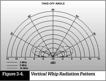
on just some of the more common types. The vertical whip antenna is usually
adequate for ground wave circuits, since it is omnidirectional, has low
take-off angles, and is vertically polarized. A typical vertical whip radiation
pattern is shown in Figure 3-4. A reflector, consisting of a second vertical
whip, can add directivity to the radiation pattern of a whip. One of the
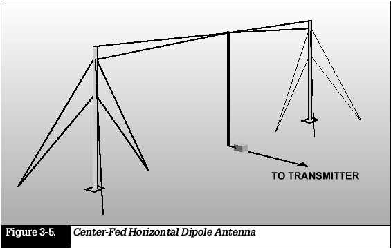
most versatile types of HF antenna is the half-wave
dipole, which
is basically a length of wire equal to one-half the transmitting wavelength.
The dipole can be oriented to provide either horizontal or vertical (center-fed)
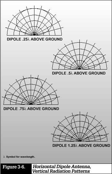
polarization. Figure 3-5 shows a center-fed horizontal dipole antenna.
The radiation pattern can change dramatically as a function of its distance
above the ground. Figure 3-6 shows the vertical radiation pattern of a
hori-zontal dipole for several values of its height (in terms of transmitting
wavelength) above the ground. A vertical dipole can often be used effectively
on ships or
vehicles.
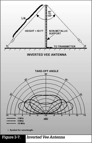
An inverted vee (sometimes called a drooping dipole) produces a combination
of horizontal and vertical radiation with omnidirectional coverage. See
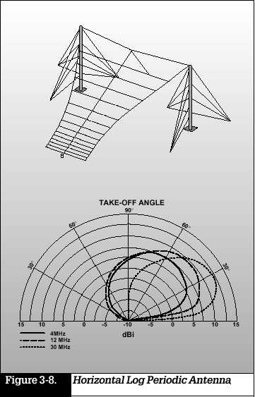
Figure 3-7. Directional antennas range from simple single-wire configura-tions
like the inverted vee to elaborate multi-wire arrays, includ-ing horizontal
and vertical log periodic systems; see Figure 3-8. Directional antennas
are often used in point-to-point links. In
systems requiring
point-to-point communications to widely dispersed stations, rotatable directional
antennas may be used. Sky wave communications between relatively closely
spaced stations may require antennas specially designed for this purpose.
These near vertical incidence sky wave (NVIS) antennas have a very high
take-off angle, radiating RF energy nearly straight up. The radio waves
refract downward to the earth in a circular pattern. NVIS antennas provide
omnidirec-tional coverage out to about 600 km.
SUMMARY
A radio system consists of a transmitter, receiver, and antenna group.
The transmitter group consists of an exciter and power ampli-fier. The exciter includes a modulator, carrier generator, and frequency translator.
The receiver group consists of an RF input filter/amplifier, frequency converters/IF amplifiers, demodulator, and local oscillator.
Antenna selection is critical to successful HF communications. Antenna types include vertical whip, dipole, and directional.
An antenna coupler matches the impedance of the antenna to that of the transmitter, transferring maximum power to the antenna.
The gain of an antenna is a measure of its directivity its ability to focus the energy it radiates in a particular direction.
Antenna radiation patterns are characterized by nulls (areas of weak radiation) and lobes (areas of strong radiation).
Low antenna
take-off angles are generally used for long-haul communications; high take-off
angles are used for shorter-range
communications.