C.1 Station Reference Frames
There are a multitude of coordinate frames being used on the Station to coordinate activities such as robotics operations, payload operations, and the Stations United States (U.S.) Guidance, Navigation, and Control (GNC) software processing. Furthermore, both the Russian and American GNC software use different reference frames.
However, for
the purpose of providing a common, generic standard for all crew displays
and crew/ground communications, a single, standard reference frame has
been designated. All activities requiring reference to Station body-centered
coordinates should reference the Space Station Analysis Coordinate System
specified later in this document. Also, overall crew/ground communications
on attitudes should be described based on the standard Euler angle sequence
for Station of yaw, then pitch, then roll from a 0,0,0 Local Vertical/Local
Horizontal (LVLH) coordinate system. (In some cases, communications may
also be based on Yaw, Pitch, and Roll
(YPR) from
a 0,0,0 X-Axis Perpendicular to Orbit Plane (XPOP) attitude.) Note that
this is different from the Space Shuttle, which uses a roll, pitch, and
yaw Euler sequence.
Although these are the most important coordinate systems for Station operations, all coordinate systems relevant to both U.S. and Russian Orbital Segment (ROS) GNC operations are covered in this appendix.
The J2000
and LVLH reference frames are commonly used by GNC to describe the Stations
attitude, and an international agreement requires that the GNC interfaces
between the ROS and U.S. GNC systems occur in these frames. X-Axis Perpendicular
to Orbit Plane (XPOP), a special reference frame for Station orientation
used during the early assembly period, is briefly
outlined
below and then covered in more detail for operational impacts later in
the GNC Training Manual. Information on all the other frames is provided
to distinguish between the reference frames used by prior ROS and U.S.
programs. More detailed information on all of the U.S.
Station reference frames can be found in SSP 30219, Rev. D, Space Station Reference Coordinate Systems. (Note: Detailed Russian coordinate systems information will possibly be referenced in Rev. E of SSP 30219 or in the Gagarin Cosmonaut Training Center (GCTC)-supplied Motion Control System Training Manual.)
C.2 U.S. Reference Frames Used By GNC
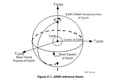
C.2.1 J2000
J2000 is an inertial right-handed Cartesian coordinate system centered on the Earth (see Figure C-1). The X-axis is directed towards the mean vernal equinox at noon on January 1, 2000.
The Z-axis points out the North pole along the Earths rotational axis. The Y-axis completes
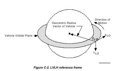
C.2.2 Local Vertical/Local Horizontal
The LVLH reference
frame is shown in Figure C-2. The LVLH frame has its origin at the vehicle
center of mass. The positive Z-axis points nadir (toward the center of
the Earth). The positive Y-axis points perpendicular to the orbit plane,
opposite the orientation of the orbit angular momentum vector. The positive-X
axis is the horizontal projection of the velocity
vector and
completes the right-handed coordinate system. Notice that because the velocity
vector rotates, to remain tangential to the orbit, the LVLH system also
rotates about the Earth.
Compared to a J2000 frame, the LVLH frame for the Station, shown in the Figure C-2, makes one complete rotation during each orbit. This results in a 4 deg/min pitch of the LVLH frame, with respect to the J2000 coordinate system.
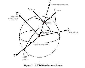
C.2.3 X-Axis Perpendicular to Orbit Plane
The X-Axis Perpendicular to Orbit Plane (XPOP) reference frame is shown in Figure C-3. XPOP is a quasi-inertial reference frame that can be visualized by a 90° yaw of the LVLH frame at orbital noon. The X-axis points out of plane, while both the Y- and Z-axes lie in the orbital plane. Note that unlike LVLH, which is rotating with the Station as the Station rotates about the Earth, XPOP remains fixed with the Station X-axis pointing out of plane and the Z-axis is aligned with the orbit noon vector. XPOP is a quasi-inertial reference frame, because as the orbital plane slowly regresses, the XPOP reference frame also regresses to keep the X-axis pointing out of the orbital plane.
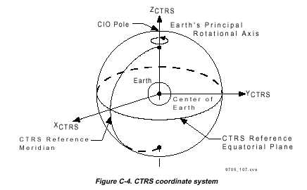
C.2.4 Conventional Terrestrial Reference System
The Conventional
Terrestrial Reference System (CTRS) is the reference system used by the
Global Positioning System. It is an updated Earth-fixed system that incorporates
polar precession. CTRS assumes a spherical Earth and does not take any
flattening factors into account. The pole of this system is known as the
CIO. The Z-axis is coincident with the Earths
principal
rotational axis, with the positive direction toward the CIO. The X-axis
passes through the intersection of the CTRS reference equatorial plane
and the CTRS reference meridian. The positive X-axis is in the direction
of the CTRS reference meridian. The positive Y-axis completes
the rotating
right-handed Cartesian system. The CTRS coordinate system is shown in Figure
C-4.
C.3 Russian GNC Reference Frames
While the Russian Motion Control System (MCS) is active, it references all MCS activities to the following coordinate systems.
C.3.1 Orbital Coordinate System
The Orbital
Coordinate System (OCK) is very similar to the U.S. LVLH reference
frame. The OCK reference frame has its origin at the vehicle center
of mass. Z-axis is pointing along the radius-vector connecting the ISS
center of mass with the center of the Earth. X-axis lies in the
orbital plane
and is pointing toward the ISS velocity vector. Y-axis completes the right-handed
coordinate system. Similar to the U.S. LVLH system, OCK also rotates
at about 4 deg/min, with regards to J2000.
C.3.2 Current Orbital Coordinate System
The Current Orbital Coordinate System (TOCÊ) is defined by taking an instantaneous snapshot of the Station body axes in the OCK frame and setting this to be the new 0,0,0 OCK axes. These newly established coordinate system axes then rotate at orbital rate.
C.3.3 Inertial Coordinate System
The Inertial Coordinate System (OCK) is equivalent to the U.S. J2000 coordinate reference frame. It is Earth centered, with X pointing to the vernal equinox of 2000, Z pointing toward the celestial pole, and Y completing the right-hand system.
C.3.4 Current Inertial Coordinate System
The Current Inertial Coordinate System (TOCK) is defined by taking an instantaneous snapshot of the Station body axes in the OCK frame and setting this to be the new 0,0,0 OCK axes.
C.3.5 Solar Orientation Coordinate System [CO]
The International Space Station (ISS) body axes are oriented relative to a solar coordinate system. A vehicle-centered system, this frame has the X-axis pointing at the center of the solar disk, the Z-axis perpendicular to the plane of the ecliptic and pointing toward the celestial pole, and the Y-axis completing the right-hand system.
C.3.6 Equilibrium Attitude Regime
In this frame,
the axes are set in such a way that during ISS flight in this coordinate
system, the integral value of the disturbing torques per one orbit is minimal.
This is equivalent to basing a coordinate system relative to an orbit-average
Torque Equilibrium Attitude (TEA), which is a
concept covered
later in this manual.
C.4 Space Station Body Axes - U.S. and ROS
It is fairly common in GNC when discussing the attitude of the Space Station to refer to the vehicle as being in an LVLH attitude or an XPOP attitude. Frequently, what is implied is that the Space Stations body axes are being controlled within an attitude envelope about the LVLH or XPOP reference frame, or are most easily visualized by describing their orientation with respect to the LVLH or XPOP reference frame.
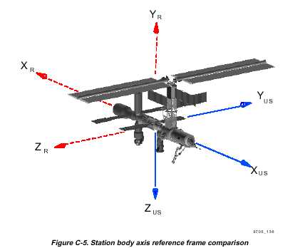
To visualize the Stations orientation with respect to the reference frame, you need to understand how the body axes are oriented on the Space Station. Body axes are a set of axes that remain fixed to the Space Station and therefore rotate with Station rotation. Figure C-5 shows how the U.S. and ROS GNC systems define the Station body axes. Both of these are just different ways to describe the Station attitude with regards to one of the reference frames.
For example,
a LVLH 0,0,0 attitude means that the Stations x, y, and z body axes are
aligned with the x, y, and z axes of the LVLH reference frame. An XPOP
20,5,5 attitude means that the Stations body axes are rotated from the
XPOP frame by a 20° yaw, then a 5° pitch, and then a 5°
roll. This
sequence depends upon the Euler angle sequence. A YPR Euler sequence of
20,5,5 is not the same as a Pitch, Yaw, and Roll (PYR) Euler sequence of
5,20,5.
C.4.1 Space Station Analysis Coordinate System
The Station
body axes are defined by the U.S., as shown in solid line on Figure C-5.
The origin is located at the geometric center of the S0 truss. The positive
X-axis points forward out of the long Station axis, the positive Y-axis
points out of the starboard truss, and the positive Z-axis
points out
the bottom of the Station (nadir), as defined by completing the right-handed
coordinate system.
C.4.2 ISS ROS Analysis Coordinate System
The Station
body axes are defined by the ROS, as shown in dashed line in Figure C-5.
The origin is located at the aft end of the Service Modules widest section.
The positive X-axis points aft out of the long Station axis, the positive
Y-axis points out the top of the Station (zenith), and
the positive
Z-axis points out of the port truss, as defined by completing the right-handed
coordinate system. The ROS MCS reports Station attitude in the Space Station
Analysis Coordinate System.
The U.S. GNC
software has a flexible user interface so that it can operate in the J2000,
LVLH, or XPOP frames while accomplishing its navigation and control roles.